AUTHORS:
Richard Davies1, Paul McCutchion1, Farhan Khan2, Hoda Amel2, Philip O’Gara3,Yaan Liu1, Oana Ghita1
1Centre for Additive Layer Manufacturing (CALM), University of Exeter, North Park Road, EX4 4QF
2Manufacturing Technology Centre (MTC) Ansty Park, Coventry, CV7 9JU
3Thales Underwater Systems, Ocean House, Throop Road, Templecombe, Somerset, BA8 0DH
The Centre for Additive Layer Manufacturing (CALM) at the University of Exeter has recently worked with the Manufacturing Technology Centre (MTC) and Thales UK, to showcase how Additive Manufacturing (AM) can be used with high performance polymers such as PEEK, to produce production parts for high value applications.
In recent years there has been rapid developments in the sector in terms of both equipment and materials. However, the challenge in identification of suitable applications still exists, together with a gap in knowledge for how best to approach building these components.
This case study attempts to showcase some of the steps required, whilst providing a brief overview of the technologies available.
Industry Developments – Additive Manufacturing with High-Temperature Polymers
High-temperature polymeric additive manufacturing was first introduced onto the market more than 10 years ago through both EOS GmbH with its EOS P 800 powder bed system and HP3 PEK material, and Ultem materials on Stratasys’ material extrusion (MEX) technology, more commonly known as FDMTM (Fused Deposition Modelling) or FFF (Fused Filament Fabrication). Recently polymeric additive manufacturing, or 3D printing, has seen a significant growth in high performance polymers with Poly Aryl Ether Ketone (PAEK) materials and new equipment coming to market, reflected in a significant increase in PAEK business opportunities as shown below.
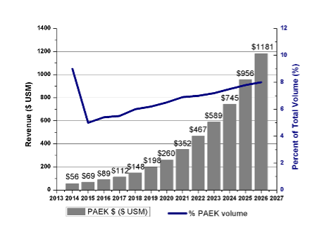
Challenges – Since their introduction, a number of challenges were identified that restricted the growth of the sector, which for the powder bed process included the high cost in machine and materials, powder recycling issues and thermal stability of the system2-3. Significant progress has been made but, although this specialist AM area is growing and has seen investments from material and equipment manufacturers, it is still to fully deliver on its expectations with limited actual parts and industrial case studies published.
Case Study: Redesign of a High-Performance Cable Guide and Conduit using AM
This EPSRC funded project was carried out through a collaboration between 3 organisations:
- CALM – a UK leading research centre for high-performance polymeric AM, at the University of Exeter
- The MTC – an independent research and technology organisation established to develop and prove innovative manufacturing processes and technologies in partnership with industry, academia and other institutions.
- Thales UK – Thales provides world-leading electronic solutions for defence applications across air, sea and land. This project worked with its UK underwater systems team, a global leader and world’s top exporter of sonars and related systems for naval forces.
It was initiated following CALM and the MTC signing a Memorandum of Understanding (MOU) in 2019 to work together on high temperature polymers with AM, which led to Professor Oana Ghita becoming the MTC’s researcher in residence for polymeric AM, funded by the Research Councils UK (RCUK). The two organisations joined forces as part of this programme, to embark on searching for prime applications. A partner of both organisations was Thales, with Thales particularly keen to establish how the technology could be beneficial for production parts, having previously used AM techniques in prototype applications. Through discussions the team was able to identify a suitable product to investigate, a cable guide and conduit for optical fibres employed in one of Thales’ underwater systems. From this, all partners worked together to develop a new design, before printing the part in Exeter’s EOS P 800 system, using PEEK material.
Get your FREE print subscription to TCT Magazine.
Exhibit at the UK's definitive and most influential 3D printing and additive manufacturing event, TCT 3Sixty.
Previous cable guides were metallic components of simple design as they were routing conventional copper conductors. The use of optical fibres required a more complex geometry to protect the fibres. Thales designed a single-part assembly that would utilise Victrex 450 PEEK (for corrosion control) and incorporated an internal S-channel to guide the fibres from the underside and out through the cage structure. However, this structure could not be achieved through conventional manufacturing routes, which necessitated the use of a four-part assembly to achieve the same result with the follow-on increase in part count and increased assembly operations.
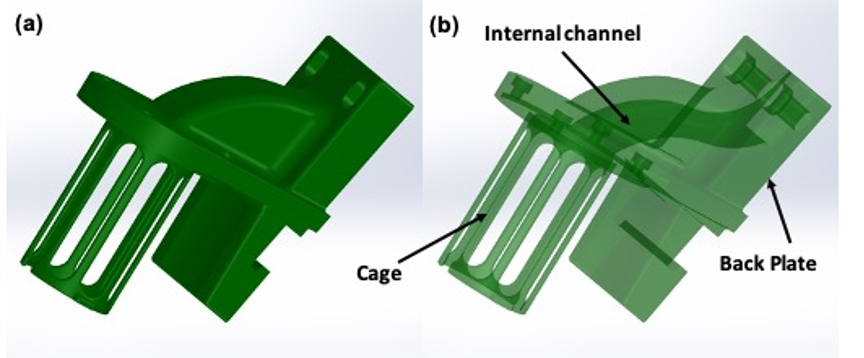
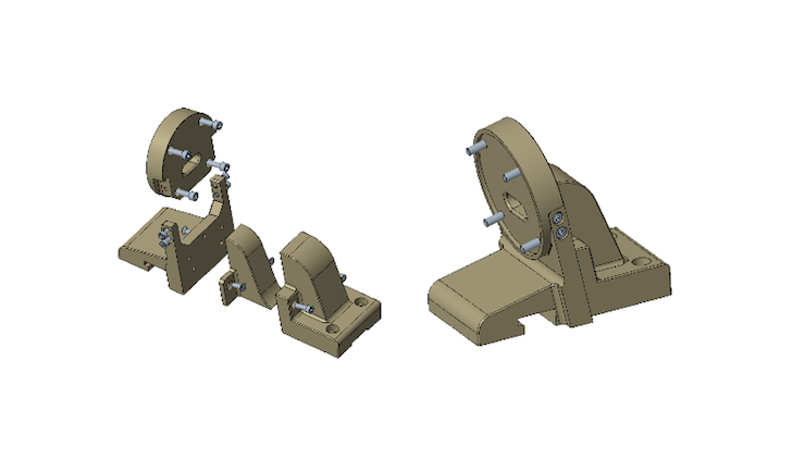
The cable guide (cable input) connects to a cylindrical housing which protects the hardware for taking signals out of an array as seen below.
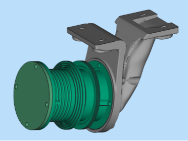
It was expected that AM could further enhance the product (e.g. reduce mass), whilst also providing improvements to the manufacturing, such as reducing material waste and assembly time. Another incentive in exploring additive manufacturing is the low number of parts required per year (in low hundreds). AM offered an improved manufacturing process with the option of using the same grade of material.
The R&D Process
The R&D process followed included:
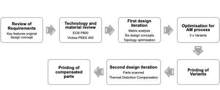
Review of requirements
The component had two key features which needed to be maintained:
- The internal channel, of defined radius and suitable finish to guide the cabling through, and the cage dimensions incorporating an O-ring seal.
- The component is required to resist pressure (20 MPa bulk compressive strength), have good water resistance (no porosity or porous structures) and achieve a finish of 0.8 µm Ra (at the O-ring seal face) to allow good adhesion during additional process steps which includes over-moulding with elastomeric polyurethane (PU).
Technology and material review
The two additive manufacturing polymer-based technologies available at CALM, in Exeter, are Powder Bed Fusion (PBF) and Material Extrusion (MEX). The PBF system was selected for this project as the inherent porosity of the parts produced by the MEX technology was not considered a viable option, although developments in this area may provide opportunities in future. For example, amongst the extrusion-based technologies, Bond 3D (Enschede, Netherlands) is developing a system that may be able to deliver virtually void-free PEEK parts4. The use of PBF was also an opportunity for the Thales engineers to understand the design and manufacturing constraints of this process with high performance polymers, a less accessible technology in the UK and Europe than the MEX technology.
The EOS P 800 high-temperature system was selected for the process. This uses a CO2 laser that can run at temperatures up to 385 °C5. The PBF process is complex and there are less manufacturers available in this space than MEX. EOS and Farsoon (Stuttgart, Germany) are the main high temperature PBF manufacturers, with Farsoon able to achieve high temperatures up to 280°C for PA6, PA66 and PEI with their PBF powder bed fusion process (ST252P system)7. EOS has also recently launched an upgraded system, the EOS P 810, which is suitable for serial production of composite materials8 based on HT23, a carbon fibre reinforced PEKK grade.
Materials - Initially the EOS P 800 was launched for use with EOS HP3 PEK, a powder specifically designed for use in the machine9 and it was the only commercial grade available worldwide. Since then, other materials have been made available from material suppliers. In this particular case study, Victrex PEEK 45010 has been used in powder form. Although not a commercial laser sintering grade, PEEK 450 has been qualified for use in Thales and therefore it is a material well understood by the material engineers and so was selected for both comparison purposes and for ease of integration into the organisation. However, it is accepted that other materials, including alternative materials from Victrex, may provide some improvements in performance. The CALM team also has hands-on experience of PBF with 450 PEEK and this knowledge helped optimise both the design and manufacturing process, with previous work carried out at Exeter providing the necessary input property data required for the redesign and optimisation11.
Initial design review & 1st design iteration
The use of Additive Manufacturing enables conventional manufacturing design constraints such as the constant wall thickness, sharp corners (internal or external) or internal ducts to be removed, with designers able to explore new concepts. The 1st redesign step started by following standard design guidelines and comparing different design concepts based on: 1) FEA/topology; 2) internal lattice; 3) external lattice; 4) surface lattice; 5) cage compliance redesign and 6) tube thinning, in relation to a number of factors. These included redesign lead time, technology readiness level (TRL), the buildability in PEEK PBF and the ability to demonstrate AM capabilities such as freeform design and light weighting.
The part was optimised for maximum stiffness subject to a reduced volume fraction. This was based on an initial assumed pull loading on the cage section. The results showed more than 30% mass reduction. The topology results were then modified using NUBRS (Non-Uniform Rational Basis Spline) modelling in order to achieve a smooth geometry.
A selection of designs was presented with some designs discounted for a number of reasons. E.g. internal lattice structures would cause difficulty in post process powder removal and external lattice structures would cause contaminated in use due to open cells. Following FEA and topology optimisation, concept 1 was selected. Combining the results of the FEA with the topology optimised, the 1st redesign is shown below.
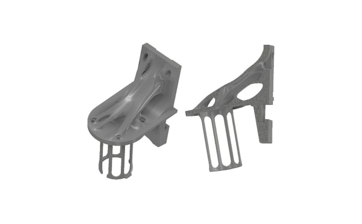
Design for the AM process
The next step was for the collaboration to work together to optimise the design for manufacturing, taking into account requirements for printing on the P 800 system with a number of design considerations and optimisation steps taken including:
- Post-processing considered – e.g. avoiding small gaps or air pockets for PU coating, powder removal and machining processes (2 mm machining stock).
- Material properties and powder bed density.
- Nesting arrangement of the parts to avoid excess heating of surrounding powders/adjacent parts generated during building.
- Presence of thick walls to be reduced and optimised – The thickness of some regions such as the back-plate were more than 10 mm, which can be a concern for the PEEK PBF process due to thermal distortion. As such the back-plate was thinned and the wall thickness of the component optimised.
- The back-plate was modified to allow four connection points.
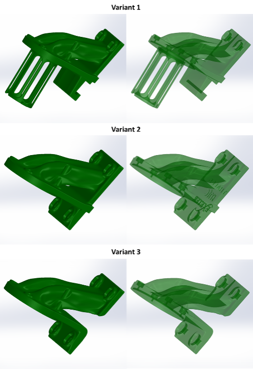
Three variants were shortlisted after further optimisation for the powder bed process as shown below.
Printing of the test parts
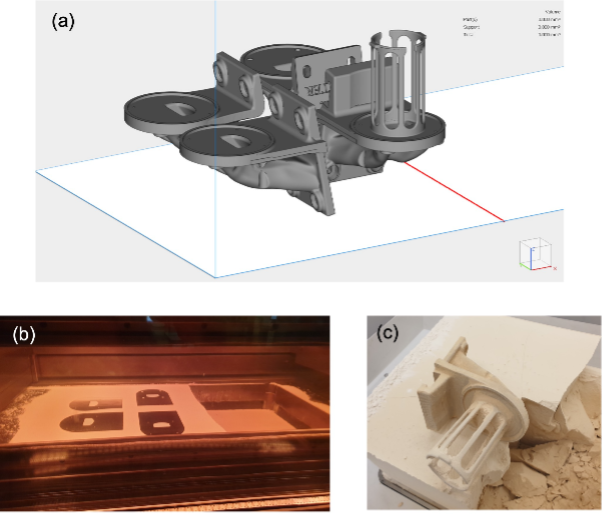
The variant parts were then printed at Exeter, using the EOS P 800 PBF system in the 50% reduced chamber configuration, to reduce material consumption. Four parts with four different designs were printed simultaneously for evaluation, in 60 hours manufacturing time from start to finish. This included powder loading, printing, cooling down, powder removal and cleaning.
The image above shows the three variant parts that were printed. The image below shows the printing process and powder removal process.
2nd design iteration, optimisation and distortion compensation
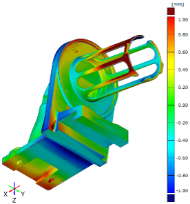
The parts were scanned at the MTC to determine deviation from the original design and any shrinkage/warpage incurred during the process. The scanner used for the parts was a GOM ATOS Tipple Scan which is a 3D blue structured light scanner. It uses reference points on the part for alignment to connect multiple scans together to create mesh data. The MTC has a range of equipment for tactile and optical measurement of parts for dimensional and surface metrology along with X-ray computed tomography (XCT) for non-destructive testing (NDT).
Due to the thermal distortion resulting from the AM process, two methods of pre-distorting the new CAD designs were attempted: a) Capturing 3D scan of the printed part and applying pre-distortion based on the deviation from the CAD model and b) Exploring pre-distortion using Hexagon’s Digimat software12. As an example, the image below shows deviations larger than 1mm of Variant 1.
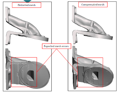
In the 2nd design concept, further modifications were suggested by the CALM and MTC teams to continue to optimise parts for manufacturing and compensate for additional shrinkage and distortion. The quality of the models was affected by several factors such as starting scan or mesh resolution, size of features and sharpness of corners. Some loss of features was experience in both methods as shown below.
Printing of the 2nd design iteration
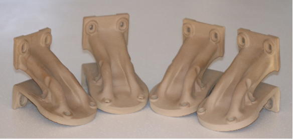
The second design with further optimisation was then printed again by the CALM team, using the same grade of material Victrex PEEK 450 and EOS P 800 system as shown below.
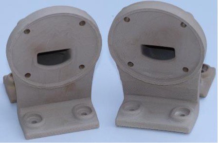
The back plate surface connecting to the baseplate showed differences in finish and slight subtle irregularities on the surface due to missing areas and defects created during the transfer of the scan model to the compensated model (see below).
Case Study Evaluation
This case study contributes towards the evaluation of high performance polymeric AM technologies within Thales, guiding engineers in their choice of materials and AM processes and will help define the next generation of products and manufacturing processes.
The final parts were inspected by the Thales team and they confirmed the expected benefits had been successfully realised, including 1) elimination of the assembly stage – the original design was based on four parts and, 2) reshaping of the original duct into two distinct channels which allowed the creation of a lighter part with less material wastage. The conduit was successfully attached to the additional parts within the complete system, with the internal finish of the channel providing a satisfactory surface finish for the application. The component’ back plate skins will follow a machining post-process to match the tolerances required in this application.
Dr Philip O’Gara, materials engineer at Thales explained that “It is not easy to evaluate the powder bed fusion process for high performance polymers in the UK. High performance polymeric AM in general is still emerging, and collaborations with experts in these areas at CALM and the MTC allows organisations such as Thales to stay at the forefront of knowledge and application developments. Such collaborations are also important to develop the skills of our design engineers”
The study was carried out using Victrex 450PEEK grade, a well know PEEK grade used extensively for machining, as well as injection and compression moulding, but not optimised for AM. This provided a good comparison for Thales with a material grade used by the teams and well understood. However, as the range of AM materials is growing and new PAEK grades are being developed, this case study and new ones will continue to explore optimum alternative material grades for specific applications, which will further aid manufacture and product performance.
Prof Ghita at the University of Exeter added, “This has been a great chance to collaborate with both the MTC and Thales to demonstrate the opportunity that exists within this growing sector of Additive Manufacturing.”
Dr Hoda Amel, Senior Research Engineer at the MTC also added, “Projects that bring experts and end users together are key in showcasing the potentials of AM. We at the MTC are keen to support industry in their AM journey with our in-house expertise or through collaborations with our partners”.
Collaborative research is ongoing to further expand the range of materials and processes available, whilst optimising them for emerging applications. If you would like to find out more about this EPSRC funded case study, or about the capabilities at CALM or the MTC please contact calm@exeter.ac.uk or ncam@the-mtc.org.
References
1. Wade, M. SmarTech Publishing Research Note: How PEEK and PEKK Are Expected to Become the Most Profitable Segment in AM of Advanced Thermoplastics; 2017.
2. Yi, N.; Davies, R.; Chaplin, A.; McCutchion, P.; Ghita, O., Slow and fast crystallising poly aryl ether ketones (PAEKs) in 3D printing: Crystallisation kinetics, morphology, and mechanical properties. Additive Manufacturing 2021, 39, 101843.
3. Berretta, S.; Evans, K. E.; Ghita, O. R., Predicting processing parameters in high temperature laser sintering (HT-LS) from powder properties. Materials & Design 2016, 105, 301-314.
4. Jackson, B. VICTREX TO INVEST MILLIONS TO EXPAND PAEK 3D PRINTING WITH BOND 3D. https://3dprintingindustry.com/news/victrex-to-invest-millions-to-expand-paek-3d-printing-with-bond-3d-151083/; 2019.
5. Hoskins, T.; Dearn, K.; Kukureka, S., Mechanical performance of PEEK produced by additive manufacturing. Polymer Testing 2018, 70, 511-519.
6. Sher, D. Everything about today’s PEEK ad PEKK 3D printing market - And why advanced plastics are the key to production parts https://www.3dprintingmedia.network/everything-about-peek-3d-printing/.
7. Technologies, F. Farsoon Technologies http://en.farsoon.com/solution_list01_detail/productId=27.html.
8. Galantucci, L. M.; Guerra, M. G.; Dassisti, M.; Lavecchia, F. In Additive Manufacturing: New Trends in the 4th Industrial Revolution, Proceedings of the 4th International Conference on the Industry 4.0 Model for Advanced Manufacturing, Cham, 2019; Monostori, L.; Majstorovic, V. D.; Hu, S. J.; Djurdjanovic, D., Eds. Springer International Publishing: Cham, 2019; pp 153-169.
9. Beard, M.; Ghita, O.; Bradbury, J.; Flint, S.; Evans, K., Material characterisation of additive manufacturing components made from a polyetherketone (PEK) high temperature thermoplastic polymer. Innovative Developments in Virtual and Physical Prototyping 2011, 329-332.
10. Victrex, VICTREX® PEEK 450PF data sheet. Avaiable: https://www.victrex.com/~/media/datasheets/victrex_tds_450pf.pdf. 2018.
11. Berretta, S.; Evans, K. E.; Ghita, O., Processability of PEEK, a new polymer for High Temperature Laser Sintering (HT-LS). European Polymer Journal 2015, 68, 243-266.
12. https://www.e-xstream.com/products/digimat/about-digimat


